In the water quality improvement industry, membranes are defined as physical barriers that separate solutions and allow passage of waterborne contaminants within a certain range of size, molecular mass, or even charge polarity and strength.
When driving pressure is applied, and depending on the material, pore size and electrical charge of the membrane, certain contaminants will be “selectively rejected” or “concentrated” by the membrane while water and unrejected contaminants will pass through as a “purified” permeate stream. This is the essence of membrane separation.
Membrane separation technology is an invaluable resource for residential, commercial and industrial water treatment applications.
Flow Configuration
Separation membranes are typically operated in “dead-end” or crossflow configuration. In dead-end configuration, the rejected contaminants concentrate into the influent stream and eventually accumulate against the surface and pores of the membrane. Naturally, the concentrated contaminants will inevitably clog the membrane pores entirely, so this process is reserved for applications where the cost/inconvenience of replacing fouled membrane sheets is less important than losing any of the raw fluid or where the engineered process flow design specifically calls for it. A growing segment of “dead-end” configuration is backwashable tubular or “hollow fiber” construction, which is significantly less sensitive to fouling than membrane sheets. Look for increasing market penetration of this technology as the manufacture of these tubes become more reliable and cost-effective.
In crossflow filtration, the membrane geometry is designed for contaminants to be scrubbed away from the membrane surface when the concentrated discharge stream is passed to drain or a secondary process. Leveraging the principles of Fick’s laws of diffusion, designers can manipulate macromolecule concentration molecules at the membrane surface as a function of the velocity of fluid that is flowing parallel to it.
Membrane materials and element construction
Crossflow technology is cost-effective and practical due to durable organic polymeric materials.
Those of you who have been around the industry for a few years will remember Cellulose Triacetate (CTA) membranes that were once ubiquitous. A game-changer popularized in the mid-1990’s was Thin Film Composite (TFC) which lowered total cost of ownership and increased flux at lower driving pressures. Composite membranes can be made from a number of materials, such as polyethersulfone (PES), polysulfone (PSU), polyphenylsulfone (PPSU), polytetrafluoroethylene (PTFE), polyvinyldene fluoride (PVDF), and even polypropylene (PP). The vast majority of installations these days utilize composite membranes while other materials such as ceramics made from Silica, Aluminum, Titanium and other materials are only where pH, temperature, abrasiveness, cleaning chemistry, or other operational parameters prohibit the use of polymers.
Polymeric membranes can be manufactures symmetrically or asymmetrically, but a discussion of which is outside the scope of this article. Contrary to popular belief, there are many ways to build a crossflow membrane, including type of polymer, length of membrane leaves, membrane support configuration and membrane density. These configuration options are significant in mission-critical operations, and also important when selecting regular water-filtration membranes that you are going to stake your reputation on.
Today’s mainstream membrane separation technologies can be separated into four categories of separation by relative contaminant exclusion size:
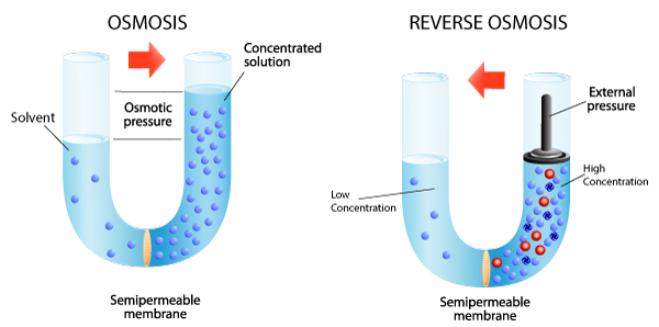
Reverse Osmosis (RO) – Sometimes called “hyperfiltration”, reverse osmosis is the finest form of filtration used today. The membrane pores are small enough to enable the reversal of osmotic pressure through ionic diffusion when sufficient external energy (pumping pressure) is applied. This reversal of osmotic pressure actually drives pure water away from molecular contaminants and enables processes like seawater desalination where sodium ions are physically removed from water; greening the desert and bringing clean, safe drinking water to places where it was previously impractical. Reverse Osmosis is also used industrially in many innovative applications such as concentrating fruit juice, concentrating whey protein, and of course wastewater sludge dewatering. While most dealers and end-users know about Reverse Osmosis separation technology, but there are other membrane separation technologies that you also need to know about.
Nanofiltration (NF) – Developed as an extension of RO, NF functions according to the same principles of ionic diffusion as RO, but with a pore-size configuration and slight surface charge that allows passage of all contaminants except divalent and larger ions. Monovalent ions such as sodium and potassium pass right through an NF membrane, allowing it to be used as a highly effective salt-free softening technology without the complications of Reverse Osmosis. NF is also highly effective at addressing semi-volatile organics such as pesticides, and removing color from water.
Ultrafiltration (UF) – Ultrafiltration is a true physical exclusion process and doesn’t rely on osmotic principles. UF membranes are categorized by their molecular cut-off rating (MWCO). The typical range of MWCO’s for UF is from 1,000 to 1,000,000 Dalton which correlates to approximately 0.005 – 0.1 micron (µm). UF is extremely effective in removing suspended solids, colloids, bacteria, virus, cysts, and high molecular weight organics like tannins. UF membranes are operated in dead-end configuration, occasional flush (forward flush and/or backflush), or crossflow configuration. Membrane configuration can vary between manufacturers, but the “hollow fiber” type is the most commonly used. Membranes in the hollow fiber type are cast into small diameter tubes or straws. Thousands of these straws are bundled together and the ends are bonded/potted into an epoxy bulkhead. The bundles are then sealed into a housing which is usually PVC or stainless steel. The sealed potting creates a separate, sealed space that isolates access to the inside of the fibers from the outside. This membrane and housing combination is called a module. A number of UF membrane assemblies on the market are BioVir certified for log reduction of pathogens in drinking water such as bacteria and virus, enabling dealers to provide safe drinking water more cost-effectively and efficiently than ever before.
Microfiltration (MF) – Microfiltration technology is deployed in both crossfiltration spiral-wound, occasional flush hollow fiber (forward flush and/or backflush), and dead-end plate & frame configurations to great success, depending on the nature of the application. This membrane technology typically has an exclusion size of 0.2µm – 1 µm and is very well suited for the removal of particulates, turbidity, suspended solids, as well as certain pathogens such as Cryptosporidium and Giardia. MF has an established industrial track-record for sterile clarification of wine and beer, whey concentration and fruit juice sterilization. In the wastewater treatment field, microfiltration is invaluable for dewatering flocculant sludge, and economically lowering BOD and COD in discharge streams. Microfiltration is also extremely effective in protecting other downstream membrane separators.
| Typical rejection capabilities | |||||
| Water | Monovalent Ions | Multivalent Ions | Macro-molecules | Suspended Solids | |
| Reverse Osmosis | √ | √ | √ | √ | |
| Nanofiltration | √ | √ | √ | ||
| Ultrafiltration | √ | √ | |||
| Microfiltration | √ | ||||
It is very important to select the appropriate pretreatment for any membrane separation process being used. Composite polymeric membranes are sensitive to oxidative damage, so special care should be taken to ensure that chlorine, ozone, and other oxidative disinfectants are not present in the water being processed. Careful consideration should also be given to macro particles and organic/inorganic contaminants in the water stream that could affect proper membrane function. As a good general rule, the smaller the pore size, the greater amount of physical pretreatment required to ensure long runtimes and economic operation.
Regardless of the membrane pore size, operational fouling is almost inevitable, even with pre-treatment. The types and amounts of fouling are dependent on many different factors, such as feed water chemistry, membrane type, membrane materials and operational process. The most common types of membrane fouling are scale precipitation and biofouling. Fouling causes a decrease in flux, which in turn requires greater pressure against the membrane to produce a satisfactory permeate flow rate. As fouling worsens, the increased pressure (energy) requirement will cause the operating cost to increase significantly and possibly even blind the membrane completely leading to significant damage and operational failure.
It is critically important that you either secure the education you need to ensure proper system selection, design and deployment, or work with vendors who you can rely on to help before getting yourself into trouble by making uninformed decisions. The WQA’s Modular Education Program (MEP) offers a great starting-point for learning more about RO and other membrane separation technologies.
Some well-meaning but misinformed people accuse membrane separation systems of being “wasteful”, since water is used to clean the membrane/s during operation. I disagree with the negative description of drain concentrate water as “wasted water”, since it really is not. Saying that a membrane separator wastes water is akin to saying that a tree dropping its unpicked fruit is wasteful. The fruit returns nutrients to the earth and feeds the tree, which then grows more fruit. Discharge water from a membrane separation system is also not “lost forever”, it will return through the building’s drainage system to a municipal plant, or back to the earth in an off-grid application or can be repurposed in-process by design. We can’t ignore the “opportunity cost” of the water though, since it has to be cleaned, stored, treated, pressurized, and distributed before it enters the membrane separator. Since the discharge from a potable water membrane separator is also sanitary potable water (this is obviously not considered wastewater, since it is never in contact with soils, dirt, or biological contaminants; it is merely concentrated clean water), the opportunity cost of the discharge can be recovered through innovative reuse techniques such as graywater recovery, blending with harvested rainwater, repurposing in secondary process or used as landscape irrigation.
Membrane separation systems are an environmentally friendly technology and another valuable tool in lowering the overall environmental impact of our projects.
Glossary:
Dalton – The unified atomic mass unit (symbol: u) or Dalton (symbol: Da) is the standard unit that is used for indicating mass on an atomic or molecular scale (atomic mass). One unified atomic mass unit is approximately the mass of one nucleon (either a single proton or neutron) and is numerically equivalent to 1 g/mol. It is defined as one twelfth of the mass of an unbound neutral atom of carbon-12 in its nuclear and electronic ground state, and has a value of 1.660539040(20) × 10−27kg.
Fick’s laws of diffusion were derived by Adolf Fick in 1855. Expressed as follows: They can be used to solve for the diffusion coefficient, “D”. Fick’s first law can be used to derive his second law which in turn is identical to the diffusion equation. Fick’s first law relates the diffusive flux to the concentration under the assumption of steady state. It postulates the concept that a solute will move from a region of high concentration to a region of low concentration across a concentration gradient. Fick’s second law (non-steady state Diffusion) predicts how diffusion causes the concentration to change with time. While Fick holds that flux is directly proportional to the concentration gradient, the diffusion coefficient “D” is affected by temperature and pressure.
Flux is the rate of mass transfer across unit surface area of barrier and mathematically expressed as: J ≡ atoms/area/time.
Micron (µm) – One millionth of a meter. One Inch is equal to 25,400 micron.
Plate and Frame – Also known as a “membrane filter plate”. This type of filter press typically consists of alternating plates and frames supported by rails. A pressure pump is used to deliver liquid to be filtered (slurry) into each of the separating chambers. For each of the individual separating chambers, there is one hollow filter frame separated from two filter plates by filter cloths. The slurry flows through a port in each individual frame, and the filter cakes are accumulated in the hollow frame. As the filter cake thickens, the filter resistance increases as well. The filtration process is halted once the optimum pressure difference is reached. The filtrate that passes through filter cloth is collected through collection pipes and stored in the filter tank. Filter cake (suspended solid) accumulation occurs at the hollow plate frame, then being separated at the filter plates by pulling the plate and frame filter press apart. The cakes then fall off from those plates and are discharged to the final collection point.